RF Signal Source: a short introduction
Signal Source is not really part of DAS. But without signal, DAS will not work. So let’s talk about RF Signal Source or RF Source for short.
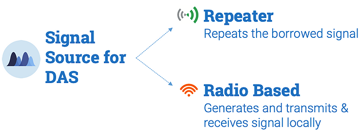
For DAS, there are 2 types of Signal Sources:
Repeater based – as we discussed under DAS 1.0, repeaters basically take signal from another signal source and then repeats or amplifies it.
Radio based – radio generates, transmits and receives signal.
There are 2 types of signal sources for DAS
Then there are 2 types of radio based signal source used for DAS:
Base Station or BTS (which stands for Base Transceiver Station). Transceiver comes from 2 words - transmits & receives.
Small Cell
The biggest differences between Base Station and Small Cell are that base station has:
More power output
Bigger in size
More capacity for calls
So in a way, if small cell is a BMW Mini, BTS is a monster truck.
Common parts of a typical RF Source
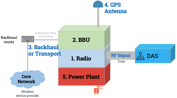
At the core all radio based RF Sources are very similar from components perspective. They all have 5 common parts:
Radio: At the core of the Radio Based Signal Source is obviously Radios. Radio transmits and receives signal that makes the cell phones work. Radio is frequency specific – i.e., only works on frequencies it’s built for. Radios produce RF Signal that feeds the antenna, and in our case the DAS. This connection is of coaxial cable, since coax carries RF signal. These radios are commonly known as RRH or RRU or Remote Radio Unit.
BBU: A very essential part of signal source is BBU or base band unit. BBU has DSP(Digital Signal Processor) that converts signals between analog and digital signals. BBU is like the orchestrator in a symphony. It generally controls, synchronizes, and processes all operations needed for the radio – including GPS information, power management, transport module management etc.
Backhaul or Transport: When you make calls, signal source needs to be connected to the core network of the wireless service provider so that it can take your voice or data information and send it to the core network. Core network connects your phone to the person or website you are trying to reach. This connection with the core network is managed by transport module in the signal source. There are multiple different routers in this connection and fiber is commonly used as transmission media for this link. This assembly of routers and connection is called ‘backhaul’ or ‘transport’. ‘Backhaul’ because we are hauling data back and forth (i.e., may be a Texan term:)
GPS: Operator's core network uses GPS signal or timing for synchronizing all communication. You may probably know that GPS timing is synced globally. So, radios need GPS timing to be in sync with its mother ship or core network. In most cases GPS antennas will be placed on the roof. Sometimes, you may find that the wireless service providers just pull the timing information from the ‘backhaul router’ instead of the GPS. In those cases, GPS antenna will not be needed.
Power plant or module: Like any other electronics, radios and BBU need electrical power to run. There will be a power module that can take power from outside (for example, building) and feed the radios and other active electronics.
For a base station, common parts of a power module are:
Rectifier which converts building AC power to DC power.
Distribution and breaker panels to supply power to different electronics connected to the module.
Back-up batteries to supply power to the signal source when building power is not available.
For a small cell which requires much lower power, the whole power module could be a AC to DC converter with some embedded power distribution capabilities.
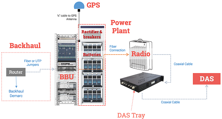
Bonus content : one more boring block diagram :)
In the above picture, I’m showing a combination of real picture of signal source and block diagram style connections to give a better sense of signal source.
Signal source, in this case, is a base transceiver station or BTS. Also, this belongs to only 1 operator. So, if the DAS is multi-operator or multi-carrier DAS, then there will be other signal sources that will need to be connected to the DAS.
Radio unit here is a stand-alone module. Although it is the main part of the Signal Source it’s often physically separated from the rest of the signal source. Usually there will be multiple radios, but for the sake of simplicity, I am just showing one radio unit. Radios can usually be rack mounted, or mounted on a wall or pole. Radios are connected to the DAS via coaxial cable and goes through a DAS Tray. DAS Trays basically takes the high output power from the radio and reduces it so that it is within the input range of the DAS.
The whole 19” rack is for power plant. We have rectifiers and breakers in the top and several strings of batteries for back-up power.
BBU is on this 19” rack. Radios are connected to BBU via fiber cable. BBU is also connected to GPS antenna via coaxial cable.
And then there is a backhaul assembly shown as a block diagram and it connects the BBU to the core network.
Related Posts:


